
Product Description
Product Description
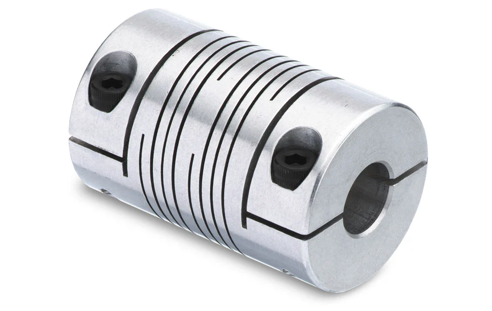
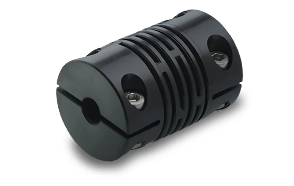
CNC Machining Milling Turning Aluminum Stainless Steel Low Force Link Slimline Strain Sensor Connect Body Liner Stage Liner Stage Thread Adaptor Beam Coupling
Product Parameters
| Processing | CNC Machining, CNC Milling and Turning, Drilling, Grinding, Stamping, Tapping, Bending |
| Surface Finishing | Electroplating, Anodizing, Polishing, Chrome Plating, Zinc plating, Nickel plating, Electrophoresis, Sandblasting, Passivation, Powder Coating, Painting, etc. |
| Certification standards | ISO9001:2015 IAFT16949:2016 |
| Service type | OEM and ODM |
| Tolerance | +/-0.005mm |
| Surface Roughness | Ra0.8 |
| Dimensions | According to Customer’s Drawing |
| Processing Equipments | CNC Machining Center, CNC Milling Machine, CNC Turning Machine, CNC Gantry, Vertical CNC center, Horizantal CNC center, Drilling Machine,Grinding Machine, etc. |
| Testing Equipments | CMM,Laser Precision Detection Projector, Pull Tester, Automatic Optical Inspector, Salt Spray Tester, Durometer, Tensile Machine Calipers |
| Application | Automotive industry, Medical DeviceS, UAV Industry, Communication Electronics Appliance, Robot, Mold Components Processed and Fixrure, 0il, Gas and Other Heavy Equipments. |
| Drawing Format | PDF/JPEG/AI/PSD/CAD/Dwg/Step/LGS |
| MOQ | 1 piece |
| QC Policy | 100% inspection with report, random inspection before shipment, third-party inspections can be provided CHINAMFG request |
| Packaging | PE bags or bubble bags, boxes, cartons, pallet or as per customers’ requirements |
| Trade Terms | EXW, FOB, CIF, As per customers’ request |
| Payment Terms | L/C, T/T, D/P, Western Union, Paypal, Money Gram, etc. |
| Delivery Time | 7-14 working days after deposit payment received for samples,official orders negotiable |
| Production Capacity | 1000000pcs/Months |
Company Profile
Production Line
Equipments List
Certifications
FAQ
1: Are You a Manufacturer?
Yes, we specialize in manufacturing of CNC machining parts over 20 years.
2. When Can I Get the Price?
Quotation will be provid within 24 hours after inquiry is received with full product information and drawing.
3: How Long is Your Delivery Time?
It’s depends on the products requirements ang quantity. Normally the mass order lead time is around 14-20days.
4: How Can You Asure the Quality?
100% inspection and we could provide full inspection reports as customer requests before shipment.
5: Do You Provide Samples ?
Yes, we can provide samples, please provide full product information and drawing.
6: Why Choose Us?
We have advanced technology and equipment, world-class team for techincal and aftersales service. We provide high quality product ,competitive price with fast lead time
/* March 10, 2571 17:59:20 */!function(){function s(e,r){var a,o={};try{e&&e.split(“,”).forEach(function(e,t){e&&(a=e.match(/(.*?):(.*)$/))&&1

Simultaneous Handling of Axial Motion and Angular Misalignment by Beam Couplings
Beam couplings are designed to handle both axial motion and angular misalignment simultaneously in motion control systems. Their unique helical beam design allows them to accommodate various types of misalignment, providing flexibility in multiple axes. Let’s explore how beam couplings achieve this:
1. Axial Motion:
Beam couplings can compensate for axial motion, which occurs when the two connected shafts are not collinear and have some linear offset along their common axis. The helical beams of the coupling can elongate or compress to absorb the axial movement between the shafts. This axial flexibility enables the coupling to maintain a continuous and efficient connection even when the shafts experience slight linear displacement.
2. Angular Misalignment:
Angular misalignment refers to the situation where the two shafts are not perfectly aligned and are at an angle to each other. Beam couplings handle angular misalignment by allowing the helical beams to flex, bending at an angle to accommodate the misaligned shafts. The flexible beams can twist and adjust their shape as needed, providing a reliable connection between the shafts and transmitting torque efficiently.
3. Simultaneous Handling:
What makes beam couplings advantageous is their ability to handle both axial motion and angular misalignment simultaneously. As the shafts experience angular misalignment, the helical beams can flex to compensate for the misalignment angle. At the same time, if there is any axial motion between the shafts, the beams can elongate or compress to absorb the linear offset. This simultaneous handling of axial motion and angular misalignment allows beam couplings to maintain smooth operation and effective torque transmission even in applications with complex misalignment requirements.
It is essential to select the appropriate size and type of beam coupling based on the specific application’s misalignment characteristics and torque requirements. Properly installed and maintained beam couplings can provide reliable and efficient performance, ensuring accurate motion control and extended system life.
Beam Couplings Accommodating Different Shaft Diameters and Mounting Configurations
Beam couplings are highly versatile and can accommodate different shaft diameters and mounting configurations, making them suitable for a wide range of motion control applications. Their design and construction allow for flexibility in adapting to various shaft sizes and mounting setups. Here’s how beam couplings achieve this:
- Multiple Bore Sizes:
Beam couplings are available in various bore sizes to match different shaft diameters. Manufacturers offer a wide range of coupling sizes, ensuring that there is an appropriate coupling size available to fit the specific shaft diameter of your application. Some beam couplings come with set screws or clamps that securely fasten onto the shafts, accommodating shafts of different sizes within the coupling’s specified range.
- Clamp or Set Screw Mounting:
Beam couplings commonly employ clamp or set screw mounting methods to connect to the shafts. Clamp-style couplings use split hubs that can be tightened around the shaft with screws, providing a secure and concentric connection. Set screw couplings, on the other hand, utilize screws to press against the shaft, achieving a firm and non-marring grip.
- Step Bores and Adapters:
In cases where the shafts have significantly different diameters or when transitioning between metric and imperial measurements, some beam couplings offer step bores or adapter options. Step bores feature multiple bore sizes within the same coupling, allowing for flexibility in accommodating various shaft diameters. Adapters are also available to bridge the gap between different shaft sizes.
- Customization:
For unique or specialized applications, manufacturers may offer customization options for beam couplings. This could include modifying the bore sizes, lengths, or other design parameters to suit specific shaft dimensions and mounting configurations.
- Compatibility with Misalignment:
Beam couplings are designed to handle misalignment between the shafts. This characteristic provides additional flexibility during installation, as it can compensate for slight positioning errors or misalignment during assembly.
When selecting a beam coupling for your application, ensure that the chosen coupling size matches the shaft diameters within the specified range. Also, consider the mounting method that best suits your setup, whether it’s clamp-style or set screw-type. For applications with specific requirements, such as adapting between different shaft sizes, explore options with step bores or adapters or inquire about custom solutions from coupling manufacturers.
Overall, the ability of beam couplings to accommodate different shaft diameters and mounting configurations makes them a versatile and widely-used choice in motion control systems across various industries.
Selecting the Appropriate Beam Coupling for Your Motion Control Needs
Choosing the right beam coupling for your specific motion control needs involves considering several factors to ensure optimal performance and reliability. Here’s a step-by-step guide to help you make an informed decision:
- Identify Application Requirements:
Start by understanding the specific requirements of your motion control application. Consider factors such as the type and amount of misalignment, torque capacity, shaft sizes, operating environment, speed, and precision requirements.
- Types of Beam Couplings:
Familiarize yourself with the different types of beam couplings available, such as single-beam, multi-beam, bellows, servo disc, slit, step beam, and jaw couplings with beam elements. Each type has unique characteristics that cater to different motion control needs.
- Misalignment Compensation:
Assess the level of misalignment in your application. If you require compensation for angular, axial, and parallel misalignment, multi-beam or bellows couplings might be suitable. For primarily angular misalignment, a single-beam coupling could be sufficient.
- Torsional Rigidity:
Consider the required torsional rigidity for precise motion control. Servo disc couplings offer high torsional rigidity and low backlash, making them ideal for precision applications, while slit couplings provide more torsional flexibility and vibration dampening.
- Environmental Factors:
Take into account the operating environment, including temperature, humidity, and exposure to chemicals. Choose a beam coupling with materials that can withstand the environmental conditions of your application.
- Speed and Torque Capacity:
Evaluate the speed and torque requirements of your motion control system. Ensure that the selected coupling can handle the specified torque while maintaining the desired speed without compromising performance.
- Space Constraints:
If your application has limited space, consider compact designs like single-beam or slit couplings. These types can efficiently fit into tight spaces while providing the necessary misalignment compensation.
- Backlash and Precision:
For applications that demand minimal backlash and high precision, servo disc couplings are a suitable choice due to their exceptional torsional rigidity and accurate torque transmission.
- Vibration Dampening:
If your system requires vibration dampening to protect sensitive components or improve overall performance, consider beam couplings with features like slits or bellows.
- Customization Options:
Check if the coupling supplier offers customization options. Some manufacturers can tailor the beam coupling to meet specific application requirements, providing an optimal solution for your motion control needs.
- Consult with Experts:
If you are uncertain about the best beam coupling choice for your application, consult with motion control experts or the coupling manufacturer’s technical support team. They can offer valuable insights and recommendations based on your specific needs.
By carefully evaluating these factors and considering the advantages and limitations of each beam coupling type, you can select the most appropriate coupling for your motion control needs. Making the right choice will contribute to the efficiency, reliability, and longevity of your motion control system.


editor by CX 2023-12-27