
Product Description
transmission parts Flexible Universal Ship Shaft Flange Flexible Rub double standard rigid jaw beam universal shaft aluminum roller Chain Coupling
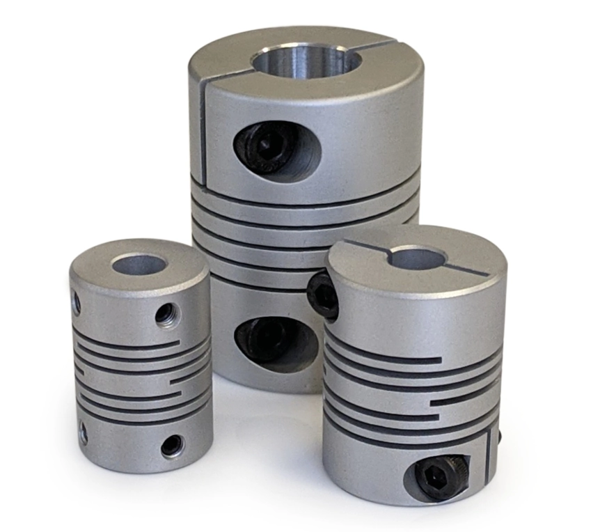
Application of Chain Coupling
Chain couplings are used to connect 2 shafts that are not perfectly aligned. They are made up of a series of interlocking links that allow the shafts to move slightly relative to each other without losing power transmission. Chain couplings are available in a variety of sizes and styles to accommodate different applications.
Here are some of the most common applications for chain couplings:
- Conveyors: Chain couplings are used to connect the drive shaft of a conveyor to the conveyor belt. This allows the conveyor to move smoothly and efficiently, even if the belt is not perfectly aligned with the shaft.
- Pumps: Chain couplings are used to connect the drive shaft of a pump to the pump impeller. This allows the pump to move fluids smoothly and efficiently, even if the impeller is not perfectly aligned with the shaft.
- Fans: Chain couplings are used to connect the drive shaft of a fan to the fan blades. This allows the fan to move air smoothly and efficiently, even if the blades are not perfectly aligned with the shaft.
- Actuators: Chain couplings are used to connect the drive shaft of an actuator to the actuator arm. This allows the actuator to move objects smoothly and precisely, even if the arm is not perfectly aligned with the shaft.
Chain couplings are a versatile and reliable way to transmit power from 1 shaft to another. They are used in a wide variety of applications, and they can help to improve the efficiency and safety of many different operations.
Here are some of the advantages of using chain couplings:
- Versatility: Chain couplings are available in a variety of sizes and styles to accommodate different applications.
- Reliability: Chain couplings are a reliable way to transmit power from 1 shaft to another.
- Cost-effectiveness: Chain couplings are a cost-effective way to transmit power from 1 shaft to another.
Here are some of the disadvantages of using chain couplings:
- Maintenance: Chain couplings require regular maintenance to ensure that they are operating properly.
- Noise: Chain couplings can be noisy, which can be a concern in some applications.
- Vibration: Chain couplings can vibrate, which can be a concern in some applications.
/* March 10, 2571 17:59:20 */!function(){function s(e,r){var a,o={};try{e&&e.split(“,”).forEach(function(e,t){e&&(a=e.match(/(.*?):(.*)$/))&&1
Specific Maintenance Requirements for Prolonging the Life of Beam Couplings
Proper maintenance is essential for prolonging the life and ensuring the optimal performance of beam couplings in motion control systems. While beam couplings are designed for reliability and low maintenance, some specific maintenance practices can help maximize their longevity. Here are the key maintenance requirements:
- Regular Inspection:
Perform regular visual inspections of the beam couplings to check for signs of wear, damage, or misalignment. Look for any visible cracks, deformations, or signs of corrosion. Detecting issues early can prevent further damage and potential coupling failure.
- Lubrication:
For couplings with movable components, such as beam couplings with elastomeric elements or bellows, proper lubrication is crucial. Follow the manufacturer’s recommendations for lubrication intervals and use the appropriate lubricants. Lubrication helps reduce friction and wear, ensuring smooth operation.
- Torque Checks:
Periodically check the tightness of the coupling’s fasteners, such as set screws or clamps. Over time, vibrations and loads can cause these fasteners to loosen. Make sure they are properly tightened to maintain a secure connection between the shafts and the coupling.
- Environmental Protection:
If the beam couplings are exposed to harsh environments, consider implementing protective measures. Shield the couplings from dirt, dust, moisture, and corrosive substances that could impact their performance and lead to premature wear.
- Alignment Checks:
Regularly check the alignment of the connected shafts. Misalignment can place additional stress on the coupling and reduce its lifespan. Make any necessary adjustments to ensure proper shaft alignment within the coupling’s specified tolerance.
- Load Capacity:
Ensure that the beam coupling is operating within its rated load capacity. Avoid exceeding the maximum torque or axial load to prevent overloading the coupling and potential failure.
- Replace Worn Components:
If any components of the beam coupling show signs of wear or damage beyond their limits, replace them promptly. Continuing to use worn or damaged couplings can lead to unsafe operation and compromise system performance.
By following these specific maintenance requirements, you can prolong the life of beam couplings, reduce the risk of unexpected failures, and maintain the overall efficiency and reliability of your motion control system. Regular inspections and proactive maintenance practices are crucial to ensure trouble-free operation and maximize the lifespan of beam couplings in various applications.
Materials Used in Manufacturing Beam Couplings
Beam couplings are commonly made from various materials, each offering unique properties that suit different application requirements. Some of the most common materials used in manufacturing beam couplings include:
- Aluminum:
Aluminum is a lightweight and cost-effective material commonly used in beam coupling construction. Aluminum beam couplings are ideal for applications where weight reduction is essential, such as in robotics or aerospace systems. They provide moderate mechanical strength and flexibility while offering good resistance to corrosion.
- Stainless Steel:
Stainless steel is a popular choice for beam couplings due to its excellent mechanical properties and high corrosion resistance. Stainless steel couplings are well-suited for demanding applications that require strength, durability, and resistance to harsh environments. They are commonly used in industries such as food processing, medical equipment, and marine applications.
- Brass:
Brass is a material known for its good electrical conductivity and moderate strength. Brass beam couplings are suitable for specific applications that require electrical grounding or where non-magnetic properties are essential. However, compared to stainless steel or aluminum, brass couplings may have slightly lower mechanical strength and corrosion resistance.
- Plastic/Polymer:
Plastic or polymer beam couplings are chosen for their lightweight and cost-effective nature. They are often used in applications where weight reduction is critical, and they offer electrical insulation properties. However, plastic couplings may have lower mechanical strength compared to metal couplings and are not suitable for high-torque applications or extreme environmental conditions.
- Carbon Steel:
Carbon steel is a robust and widely used material for beam couplings. Carbon steel couplings offer good mechanical strength and are suitable for various industrial applications. However, they may not provide the same level of corrosion resistance as stainless steel and may require proper maintenance to prevent rusting.
The choice of material depends on the specific needs of the application, including factors such as required strength, weight constraints, environmental conditions, and corrosion resistance. Manufacturers often provide a range of material options for their beam couplings to accommodate diverse industrial and commercial uses.
Handling Misalignment and Compensating for Shaft Offset in Beam Couplings
Beam couplings are designed to handle misalignment between connected shafts and compensate for shaft offset in motion control systems. Their flexible and helical beam structure allows them to accommodate various types of misalignment, ensuring smooth and reliable operation. Here’s how beam couplings handle misalignment and compensate for shaft offset:
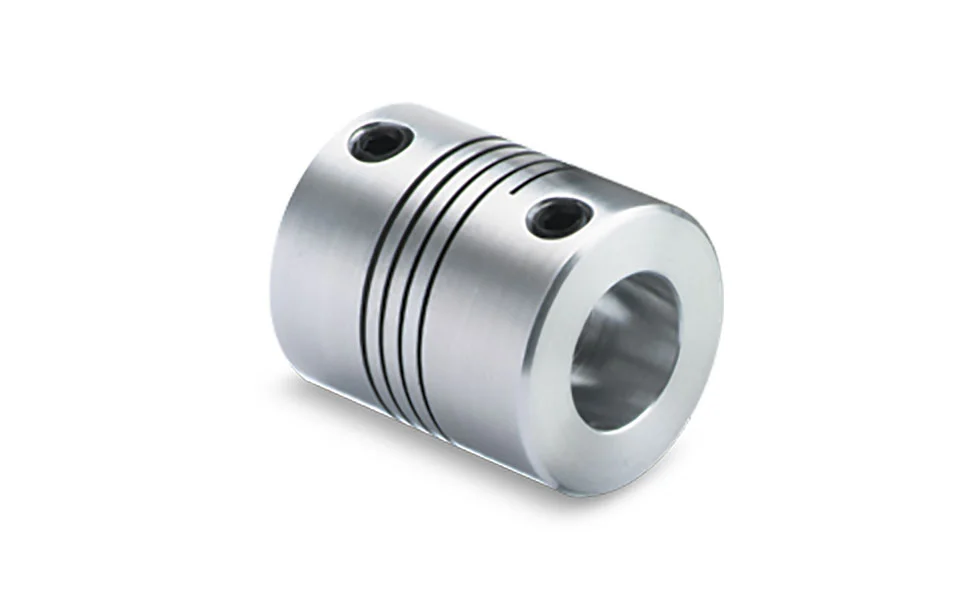
- Helical Beam Design:
Beam couplings consist of one or more helical beams, which are thin, flexible metal strips arranged in a helix shape. The helical beam design gives beam couplings their characteristic flexibility, allowing them to bend and twist in response to misalignment and shaft offset.
- Angular Misalignment:
If the connected shafts are not collinear and are at an angle to each other, it results in angular misalignment. Beam couplings can handle angular misalignment by allowing the helical beams to flex, bending at an angle to accommodate the misaligned shafts. The flexibility of the beams enables the coupling to transmit torque smoothly even when the shafts are not perfectly aligned.
- Axial Misalignment:
Axial misalignment occurs when the two shafts are not on the same axis or are not aligned in the same line. Beam couplings can compensate for axial misalignment by permitting the helical beams to elongate or compress in the axial direction. This axial flexibility allows the coupling to accommodate the offset between the shafts without causing excessive stress on the components.
- Parallel Misalignment:
Parallel misalignment refers to the situation where the two shafts are not at the same height or parallel to each other. Beam couplings handle parallel misalignment by permitting the helical beams to shift laterally. This lateral movement allows the coupling to adjust to the offset between the shafts and maintain an effective connection.
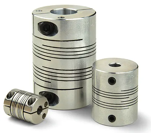
- Compensation Range:
Beam couplings have a specified range of misalignment they can accommodate. The amount of misalignment they can handle depends on the number of helical beams and the design of the coupling. Multi-beam couplings typically have a higher misalignment compensation range compared to single-beam couplings, making them more suitable for applications with more significant misalignment requirements.
- Limitations:
While beam couplings can compensate for a certain degree of misalignment, they do have limitations. Excessive misalignment beyond the coupling’s rated capacity can lead to premature wear, increased stress on the components, and reduced coupling performance. It’s essential to operate the beam coupling within its specified misalignment limits to ensure optimal functioning and longevity.
In summary, beam couplings handle misalignment and compensate for shaft offset by virtue of their flexible helical beam design. The ability to bend, twist, elongate, and shift laterally enables them to accommodate angular, axial, and parallel misalignment in motion control systems. Choosing the appropriate beam coupling type and staying within its rated misalignment range are essential to ensure effective compensation and reliable operation in various applications.


editor by CX 2024-01-09